Inventor Sheet Metal Flange Not Full Length

Solved Sheet Metal Flange Only On Partial Edge Autodesk Community Inventor
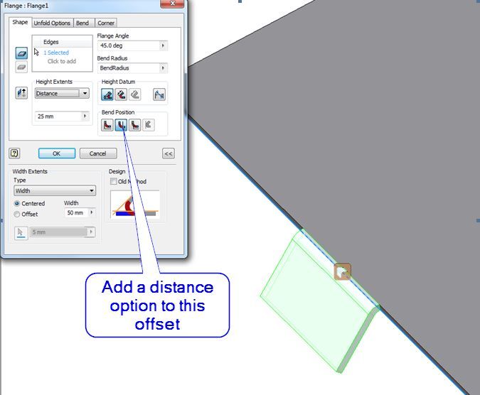
Inventor Sheet Metal Flange Offset Autodesk Community

Autodesk Inventor 2013 Sheet Metal Flange Width Options
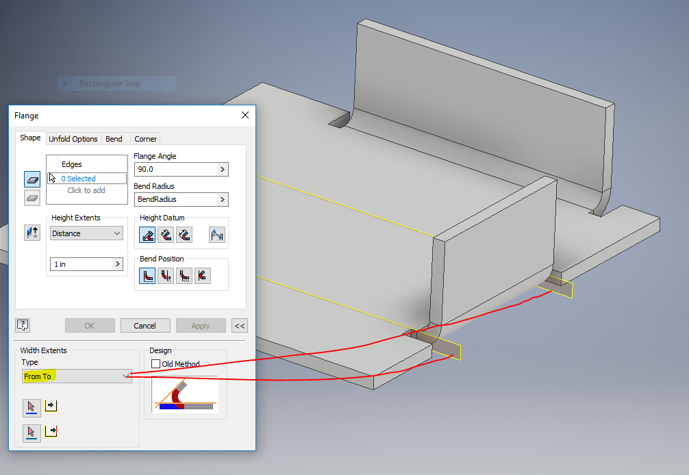
How To Move An Inventor Sheet Metal Flange Along Edge Or Certain Length On Edge Inventor 2018 Autodesk Knowledge Network
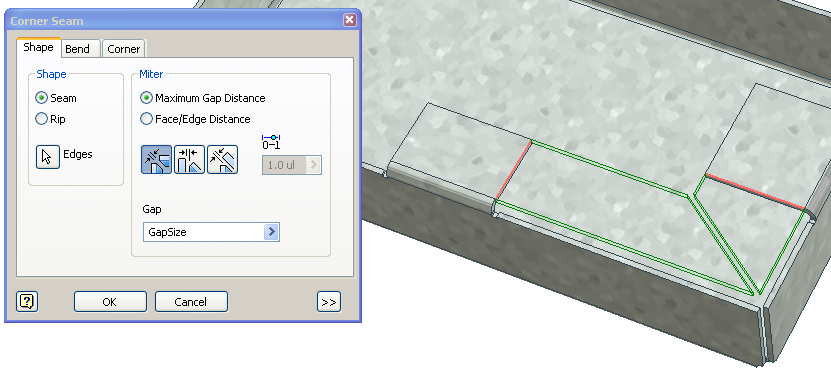
Solved Corner Of 2 Different Size Flanges In Sheet Metal Autodesk Community Inventor

Solved The Extents Feature Is Grey Out In Contour Flange Of Sheet Metal Autodesk Community Inventor

On the extents type drop down list select width.
Inventor sheet metal flange not full length.

Sheet Metal Flanges Being On The Same Plane Different Lengths Autodesk Community Inventor

Flange Feature In Inventor 2015 Youtube

Solved Sheet Metal Relief Cut Autodesk Community Inventor

Sheet Metal Flange W No Relief Autodesk Community Inventor
Source : pinterest.com
